The relation between an element’s deformation and the application of external loads to the component is what gives the stiffness concept its name: F = k? Where F is, being force applied, k stiffness of the component, and ? the deformation. This link between force and deformation is normally created in the matrix form by: {F1} = [k -k] {F2} = [-k k] With F1 and F2, being the applied forces, 1, and 2 resulting in deformation in nodes 1 and 2.
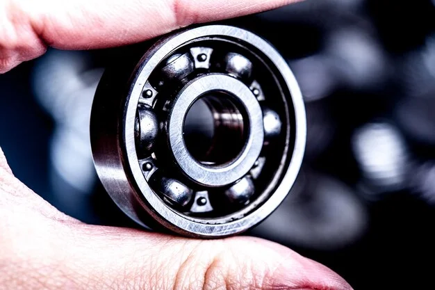
Although the stiffness matrix of a double-row angular contact ball bearing is seemingly more difficult. There are numerous publications with various mathematical models and examined bearing design geometry. The nonlinear contact characteristics inside the roller bearing are the cause of major complexity, which makes the bearing stiffness nonlinear, and load-dependent.
In the most recent publication, a 5*5 stiffness matrix is used to define bearing stiffness for a defined loading condition. For double-row bearings, the stiffness may either be identified by two matrices, or by one stiffness matrix for double-row units. Under dynamic operating conditions, the bearing must maintain a camber angle within relevant limits. Depending on the bearing rigidity or stiffness specified by the customer, under a specified bending moment. Bearing mounting flange, internal construction, etc., are designed. Following the evaluation of the bearing stiffness by FEA technology, the design is further improved. FEA Technology satisfies the stiffness requirements of the customer as well as the bearing weight, life, packing, etc. The bearing stiffness is tested using the Test Setup. Verified concerning the FEA calculation once the prototype is complete.